Views: 0 Author: Site Editor Publish Time: 2026-09-09 Origin: Site
Comminution consumes massive amounts of energy in mineral processing and cement production. Optimizing this phase starts with selecting the correct grinding media. Mismatching media to the specific feed size and target discharge creates severe operational bottlenecks. You end up with excessive energy consumption, accelerated wear rates, over-grinding, and reduced mill throughput. When particles grind finer than necessary, you waste power and generate unwanted slimes that complicate downstream recovery circuits like flotation or leaching.
Resolving these coarse grinding bottlenecks requires an objective, metallurgical comparison of grinding balls vs grinding rods. Operators must evaluate distinct contact mechanics, optimal feed ranges, application-specific performance, and material durability. Understanding how shape and mass influence kinetic energy transfer dictates plant efficiency. This technical evaluation provides the framework for matching the right media to your specific milling environment, ensuring maximum throughput and controlled particle size distribution.
Contact Mechanics Dictate Output: Grinding rods utilize line-contact crushing, ideal for minimizing over-grinding, while grinding balls rely on point-contact impact for higher reduction ratios.
Feed and Discharge Parameters: Rods generally outperform balls for feed sizes in the 1/2-inch to 1-inch range targeting a 150/200 mesh discharge. Balls are highly efficient for feeds coarser than 1-inch, intermediate finishing (e.g., 28 mesh), and fine grinding down to <400 mesh.
Material Integrity Matters: The choice between forged grinding balls and alloy steel grinding rods significantly impacts wear rates, spalling risks, and overall operational expenses across different industrial applications.
Operational Risks & Sizing: Rod mills require strict operational controls—specifically matching rod length closely to the internal mill length—to prevent rod tangling, whereas ball mills face challenges with media deformation and energy waste if the feed is improperly sized.
Coarse grinding sets the stage for all subsequent mineral liberation. Efficiency in primary and secondary milling directly dictates the recovery rates of the entire circuit. To optimize this process, operators must establish strict baseline metrics before selecting media. You cannot manage what you do not measure.
Plant metallurgists rely on specific operational parameters to evaluate mill performance:
Measure the F80 feed size coming directly from the crushing circuit to ensure it matches mill design limits.
Define the P80 target discharge size required for downstream processing, such as flotation or leaching.
Calculate the reduction ratio to determine if a single-stage or multi-stage milling circuit is necessary.
Monitor the slurry density to ensure optimal media coating and efficient kinetic energy transfer.
Track the mill power draw against the theoretical Bond Work Index of the specific ore body.
Success in comminution relies heavily on the relationship between feed size and product size. In coarse grinding, the reduction ratio typically ranges from 3:1 to 8:1. Pushing a single mill beyond this ratio forces the equipment to perform inefficiently. A drifting P80 indicates media wear, improper charge volumes, or a mismatch between the ore hardness and the media type.
The physical characteristics of grinding media products dictate how kinetic energy transfers to the ore. When the mill rotates, lifters elevate the charge. Gravity then pulls the media down, transferring crushing force to the particles. Shape and mass are the primary variables in this energy equation.
Consider the same mass efficiency principle. If you compare a steel rod and a steel ball of identical mass, their energy delivery differs completely. Rods distribute their kinetic energy along a continuous line. This spreads the force, applying just enough pressure to fracture larger particles without pulverizing smaller ones. Balls concentrate their entire mass at a single point of impact. This localized force shatters hard rock instantly but often over-grinds smaller particles caught in the impact zone.
Media density and fill volume also drive power draw. A mill charged to 35% volume with high-density steel will draw significantly more power than one charged to 25%. Higher power draw only translates to higher throughput if the media shape matches the feed size. If you use small media for large feed, the energy dissipates as heat and noise rather than crushing work. Slurry rheology plays a role here too. Thick, viscous slurry cushions the impact, reducing grinding efficiency. Thin slurry allows metal-on-metal contact, accelerating wear rates.
The fundamental difference between these two media types lies in their contact mechanics. This distinction drives every sizing and application decision in the plant. You must match the contact mechanism to the fracture characteristics of your ore.
Point-contact impact defines ball milling. As grinding balls cascade and cataract inside the drum, they strike the ore at concentrated points. This high-intensity impact shatters the rock. The result is a wide particle size distribution. You get the target mesh, but you also get a high percentage of ultra-fine particles. In a copper porphyry plant, this might be acceptable if the downstream flotation circuit can handle the fines.
Line-contact crushing defines rod milling. Rods tumble in parallel alignment. They act as a dynamic sizing screen inside the mill. The largest ore particles wedge between the rods, keeping the heavy steel slightly separated. This prevents the rods from crushing the smaller particles. The rods preferentially grind the largest rocks first. Once those rocks fracture, the rods move closer together to grind the next size down. This mechanism severely limits the production of fines, making it ideal for gravity recovery circuits.
Empirical data dictates strict feed size limits for both media types. Rods excel with feed sizes ranging from 1/2 inch to 1 inch. In this range, the rods can effectively nip the ore. If the feed exceeds 1.5 inches, the rods fail to grip the particles. They bounce off the large rocks, causing excessive rod wear, bending, and eventual breakage.
Balls handle coarser feeds better. If your F80 exceeds 1 inch, large diameter balls provide the necessary point-impact force to break the rock. Balls are also superior for finishing 1-inch feeds to intermediate specifications, such as 28 mesh, where high reduction ratios are required quickly.
Discharge capabilities vary significantly. Rod mills are sizing machines. They efficiently target the 150 to 200 mesh range. They produce a steep, narrow particle size distribution curve. Ball mills are finishing machines. They easily achieve fine grinding down to <400 mesh.
The risk of over-grinding is a critical operational factor. In base metal flotation and gold refining circuits, ultra-fine slimes coat the valuable minerals. This prevents chemical reagents from attaching, ruining recovery rates. If your downstream process cannot tolerate slimes, line-contact media is mandatory for the coarse stage.
Feature | Grinding Balls | Grinding Rods |
|---|---|---|
Contact Mechanism | Point-contact impact | Line-contact crushing |
Optimal Feed Size | > 1 inch (large balls) or fine feeds | 1/2 inch to 1 inch |
Target Discharge | Fine (<400 mesh) | Coarse/Intermediate (150-200 mesh) |
Slimes Generation | High (Wide size distribution) | Low (Narrow size distribution) |
Mill Speed Requirement | 70% - 80% Critical Speed | 60% - 68% Critical Speed |
When coarse grinding requires high reduction ratios, ball mills become the primary choice. Understanding their kinematics and metallurgical requirements ensures optimal performance. You must match the ball diameter to the top size of the feed to prevent energy waste.
Inside a rotating mill, balls exhibit two primary motions: cascading and cataracting. Cascading occurs when balls roll down the surface of the charge, causing abrasive grinding. Cataracting occurs at higher mill speeds, typically between 72% and 78% of critical speed. The balls lift high into the air and fall directly onto the toe of the charge. This generates massive impact energy. For coarse, hard, abrasive ores, cataracting is necessary. It delivers the crushing force needed to shatter large rocks. Typically, balls used in these stages range from 60mm to 150mm in diameter, depending on the F80.
Metallurgy dictates wear life. Operators must choose between forged and cast media. forged grinding balls offer superior impact toughness. The forging process compresses the steel microstructure, eliminating internal voids and porosity. This creates a highly dense, uniform ball that resists spalling under heavy cataracting impacts. Alloys like 65Mn, B2, and B3 provide the necessary hardness profile from the surface to the core.
Cast iron or steel balls are poured into molds. While high-chrome cast balls offer excellent abrasion resistance in fine cement milling, they often lack the impact toughness required for heavy-duty coarse grinding. They can fracture when dropped from high elevations inside large diameter mills. For high-impact hard rock mining, forged media provides the structural integrity necessary to survive the environment.
Ball mills face specific operational risks. Media deformation occurs when soft balls lose their spherical shape. They turn into flat polygons. Polygons do not roll; they slide. Sliding drastically reduces grinding efficiency and increases liner wear. Pooling happens when the slurry density is too high, cushioning the impact of the balls and wasting energy.
To mitigate these risks, operators must maintain an optimal ball size distribution. As balls wear down, they lose mass and impact force. You must add a calculated makeup charge of new, large balls regularly. This maintains the kinetic energy required to break the incoming coarse feed. Regular mill audits and charge sampling ensure the size distribution remains balanced. You dump the mill, sort the charge by size, and remove the scats to maintain efficiency.
Rod mills are highly specialized machines. They demand precise operational controls and high-quality consumables to function correctly. Unlike ball mills, which can tolerate some variation in feed and speed, rod mills react poorly to operational instability.
Rods operate entirely differently than balls. They rely on a tumbling motion. As the mill rotates, the rods roll over one another in a cascading fashion. They rarely cataract, as rod mills typically run at slower speeds—around 60% to 68% of critical speed. For this rolling action to work, the rods must remain perfectly parallel to each other and to the mill shell. They are typically massive, exceeding 500mm in length and weighing hundreds of pounds each.
Dimensional criticality is the most important factor in rod milling. The rod length must be specified accurately. It should be just slightly shorter than the internal working length of the mill—usually leaving about 150mm of clearance at the ends. If rods are too short, they can rotate horizontally inside the mill. If they are too long, they bind against the trunnion liners, causing severe mechanical damage.
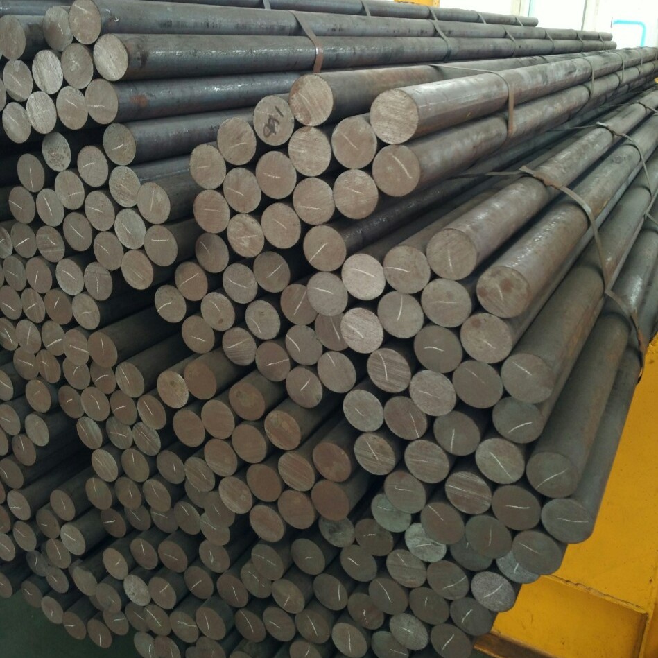
Because rods span the length of the mill, they are subjected to extreme bending forces. alloy steel grinding rods are engineered to withstand these stresses. They require specific carbon and alloy additions, such as manganese and chromium, to achieve high volumetric hardness.
Uniform heat treatment is non-negotiable. If a rod is hard on the outside but soft in the core, it will bend under the weight of the charge. A bent rod disrupts the parallel alignment of the entire mill. Conversely, if a rod is too brittle, it will snap. Broken rod pieces act like inefficient grinding balls, destroying the line-contact crushing mechanism. High-quality alloy steel ensures the rods remain straight and wear evenly down to a small diameter before breaking.
The most severe operational risk in a rod mill is tangling, commonly known as bird-nesting. This occurs when rods lose their parallel alignment and weave together into a massive, twisted knot of steel. Bird-nesting halts production completely. Clearing a tangled mill requires days of dangerous, manual labor using cutting torches.
Mitigation requires strict adherence to operational frameworks. Maintain proper mill speed; running too fast throws the rods out of alignment. Monitor feed rates carefully to ensure the rods have enough material to cushion their tumbling action. Running a rod mill empty is a guaranteed way to cause tangling. Most importantly, enforce strict quality control during procurement. Verify the straightness and length-to-diameter ratios of all incoming grinding rods before charging them into the mill.
Selecting the right grinding media requires balancing upfront procurement expenses against long-term operational efficiency. Energy and wear rates dominate this calculation. You must look beyond the initial purchase price per ton of steel.
Comminution accounts for up to 50% of a mine's total power draw. Comparing the specific energy required by both mill types reveals distinct advantages. For strict coarse sizing, rod mills are highly energy-efficient. They apply force only to the particles that need breaking.
Ball mills in the same coarse application often consume more specific energy. They waste power by repeatedly striking particles that are already at the target size. This over-grinding converts expensive electrical energy into useless heat and slimes. However, if the target discharge is very fine, the ball mill becomes the more energy-efficient option, as rods cannot effectively grind below 200 mesh.
Wear mechanisms include abrasion, impact, and corrosion. Abrasion occurs as ore grinds against the steel. Impact wear results from the media striking the liners or other media. Corrosion happens in wet milling environments where chemical reactions degrade the steel surface. You measure wear rates in grams of steel consumed per ton of ore processed. High-quality media yields a lower consumption ratio, reducing your overall consumable spend.
Logistical differences in recharging heavily influence plant availability. Adding balls is an automated, continuous process. Operators feed balls into the mill via a hopper without stopping production. Recharging rods is a manual, downtime-intensive process. The mill must be stopped, locked out, and opened. Operators use a specialized charging machine to slide new rods into the drum carefully. You must factor the cost of this lost production time into your overall media selection strategy.
To calculate true value, operators determine the cost-per-ton of processed material. This formula divides the total cost of consumed media and associated downtime by the tons of ore successfully ground to the target P80. Relying solely on the cheapest initial purchase price often leads to higher cost-per-ton due to premature wear and increased energy draw. A comprehensive metallurgical evaluation of grinding balls vs grinding rods ensures you make the most cost-effective decision for your specific circuit.
Conduct a Bond Work Index test to determine the exact hardness and crushability of your specific ore body.
Audit your current mill feed distributions to verify your actual F80 matches your equipment design parameters.
Inspect your current media charge during the next shutdown to identify signs of deformation, bending, or uneven wear.
Consult with a metallurgist to specify the exact alloy composition and dimensions required for your operating environment.
A: The main difference lies in their contact mechanics. Balls use point-contact impact, which shatters ore and produces a wider size distribution with more fines. Rods use line-contact crushing, acting as a sizing screen that preferentially breaks larger particles while minimizing over-grinding. This dictates their target mesh sizes and kinetic energy distribution.
A: You should use a rod mill when handling coarse feed sizes between 1/2 and 1 inch, and when your downstream process requires minimal slimes. They are ideal for targeting a strict 150 to 200 mesh product, as they prevent the over-grinding common in ball mills.
A: Forged balls possess superior impact toughness and uniform volumetric hardness compared to cast alternatives. The forging process eliminates internal voids. This structural integrity allows them to withstand the severe cataracting impacts of coarse grinding without spalling or shattering.
A: Rod length must be closely matched to the internal working length of the mill. They should be slightly shorter, typically leaving about 150mm of clearance at the ends. If they are too short, they will turn sideways and tangle. If too long, they will bind against the end liners.
A: Tangling, or bird-nesting, is caused by rods that are too short, running the mill at improper speeds, or running the mill empty. Breakage typically stems from poor alloy steel quality, incorrect heat treatment resulting in brittle cores, or exceeding the optimal length-to-diameter ratio.
A: Wear rate is calculated by measuring the mass of media consumed over a specific period and dividing it by the total tons of material ground during that same period. The standard metric is grams of media consumed per ton of processed material, factoring in abrasion and impact forces.
A: No. While ball mills are superior for feeds larger than 1 inch or finishing to <400 mesh, they are generally less energy-efficient for strict 1/2 to 1-inch coarse sizing. Their point-contact nature tends to over-grind smaller particles, wasting energy and producing unwanted fines.